W114 / W115 Undercarriage
by Patryk Rebisz


W114 / W115 rust repair (journey with pictures)
by Patryk Rebisz

PART I (Preparation)
PART II (Rear fender)
PART III (Left rocker panel AND rocker front)
PART IV (Left rear wheel arch)

PART V (Right rear fender understructure)
PART VI (Right rear fender)
PART VII (Right rocker panel)
PART VIII (Passenger floor)
PART IX (Passenger inner rocker)
PART X (Right rear wheel arch and rocker)
PART XI (Right fender understructure)
PART XII (Body filler)
PART XIII (Paint)
Metal explained
by Patryk Rebisz
To me, metal was always intimidating. I would open my car's engine bay and be welcomed by all sort of different surfaces. Some would be gray, some would be shinny, some would be porous while other would be slick, some would have a color while other was covered by some whitish dust. There are various metals and metal compounds used in making of your vehicles. To demystify, here is a list of what all those metals mean and how to best use and protect them.
Steel
Much of your car is made of steel sheets shaped into various surfaces. Steel is strong and flexible, relatively easy to work with and weld but also prone to rust. The moment it's exposed to moisture or worse, salt and moisture, it starts corroding. There is no way around it. Bare steel will start developing rust in as few as a few hours. The only way to avoid the "brown cancer" of rust is to separate the steel from the environment. There are numerous ways to introduce such a barrier. You can galvanize, paint, powder coat or plate the steel surface. There are other, less permanent metal protectants such as waxes or oils. Each method has its pluses and drawbacks but any is better then just leaving the bare metal exposed to environment.
Painted steel
One of the easiest methods to distance the bare metal from the environment, thus providing an attractive protection from rust, is paint. The paint must be properly applied to avoid peeling. Though it's a great way to protect the steel, its drawback is that paint is prone to mechanical damage. Scrapes and scratches loose the protective properties on the exposed metal. Even small pin-point damage lets moisture under the paint surface aggravating the damage (rust bubbles from underneath). That said, any paint is better than leaving metal bare. To weld, the paint must be removed from the metal surfaces that are to be bonded together. The area where the paint was removed (thus exposing the metal to possibility of rust), you can use weld-through primer to provide minimal rust protection. Most of the weld-through primer will melt away during welding so some other way of rust preventative must be considered in addition to the weld-through primer.
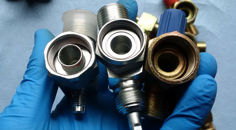
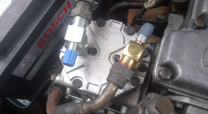
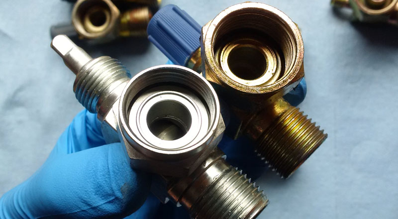
Galvanized steel
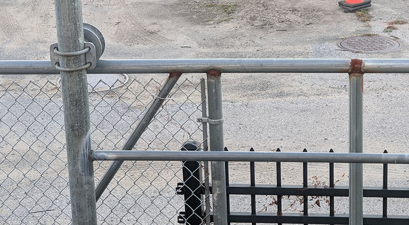
One of the best methods of protecting steel materials against corrosion is through galvanization. Galvanized steel is a clean steel with zinc metallurgically bonded to the surface, completely covering the steel with a protective coating. The most common method is hot-dip in which the parts are coated by submerging them in a bath of hot, molten zinc. This protects the underlying steel from abrasion and exposure to atmospheric conditions for many years. The corrosion of zinc is very slow, which gives it an extended life while it protects the base metal. Unlike other coatings (such as paint), small damaged areas need no touch up as small scratches are self-healing. The durability of galvanized steel provides excellent corrosion protection, one of the best currently available on the market. It provides up to 10 times the abrasion resistance of paint coatings and has superior resistance to mechanical damage. Unfortunately for auto body repairs, galvanized metal is not easy to work with. While zinc protective layer keeps metal from corroding, it also makes welding difficult. If you’re planning on welding, you are almost always going to need to grind off the galvanized layer and weld with adequate ventilation because zinc produces toxic fumes. Moreover, it's often hard to paint over galvanized metal as paint flaking car occur. Most paints will not be able to adhere to galvanized steel without the correct preparation of the substrate.
In the picture above, the sure sign of steel galvanization is the whitish powder on its surface. Notice how where the pipes were welded and zinc was striped away, heavy corrosion sets in.
Powder Coating
In powder coating, the paint dust is electrostatically attached to the part then cured under heat. Powder coating a metal object allows for a dense sturdy finish, more durable than conventional paints.
Stainless steel
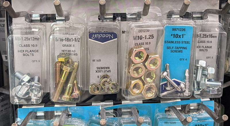
Stainless steel is an alloy of iron that resists rusting and corrosion. As a result, stainless steel is ideal for applications where corrosion resistance is essential. It generally, stainless steel is more aesthetically pleasing than regular steel because it has a bright finish that won’t fade over time. Because stainless steel contains chromium, this makes it more challenging to weld. Welding regular steel presents far fewer problems than welding stainless steels so in car restoration the stainless steel is generally reserved to use in fasteners. Car enthusiasts replace many regular steel nuts and bolts to provide long term rust protection. The limiting factor is the price as stainless steel tends to be much more expensive than regular steel.
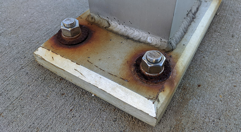
Looking at the picture above you can see stainless steel nuts and bolts still looking "new" many years after this pillar was installed at a train station right next to a river (thus exposed to atmosphere with lots of moisture). Notice the washers rusting away - clear sign that the installers ran out of stainless steel ones and used regular steel washer.
Cast iron
Many "solid" parts such as engine block or break calipers on your car are cast from iron. Just like steel, those parts can corrode very quickly if not protected. On engine parts even just a layer of oil is sufficient. The parts that shouldn't be oily, can be painted or powder coated. Cast iron is notoriously hard to weld. Welding cast iron can be problematic because of its high carbon content. During the welding process, this carbon migrates into the weld metal and/or the heat affected zone adjacent to the weld metal, causing elevated hardness/brittleness. This is how Cast Iron gets its reputation for post weld cracking.
Aluminum
Another popular metals used in cars is aluminum. Aluminum does not rust, but it does corrodes. It's actually very prone to corrosion, however, aluminum corrosion is aluminum oxide (its surface turns to whitish powder), a very hard material that protects the aluminum from further deterioration. Unfortunately, aluminum is not easy to weld for a hobbyist car re-builder because of difference in thermal conductivity, aluminum requires much higher heat inputs than steel during welding.
Plated metal/steel
Plating is a finishing process in which a metal is deposited on a surface. Plating is used for corrosion inhibition, to decorate parts, to improve solderability, to harden, to reduce friction and to improve wearability. Many parts of the engine and many bolts were plated. Many plated parts gain a strong, durable outer layer greatly hampering rust.
You have a bew basic plating process in the car rebuilding:
Zinc plating - one of the easies processes that prvides a decent rust protection. Parts turn out often shinny silver.
Yellow Zinc - somehow similar to zinc plating but much stronger to mechanical damage and around 3x more rust preventive.
Nickel plating - produces a very string, rust resitant surface.
Chrome plating - a finish treatment adding a thin decorative layer over underlaying metal to make a shinny and very strong surface finish.
Brass
Brass is the generic term for a range of copper-zinc alloys with differing combinations of properties, including strength, machinability, ductility, wear-resistance, hardness, color, electrical and thermal conductivity, hygiene and corrosion resistance. Because brass is softer than regular metal it tends to be used in bushings and other "wear" applications.

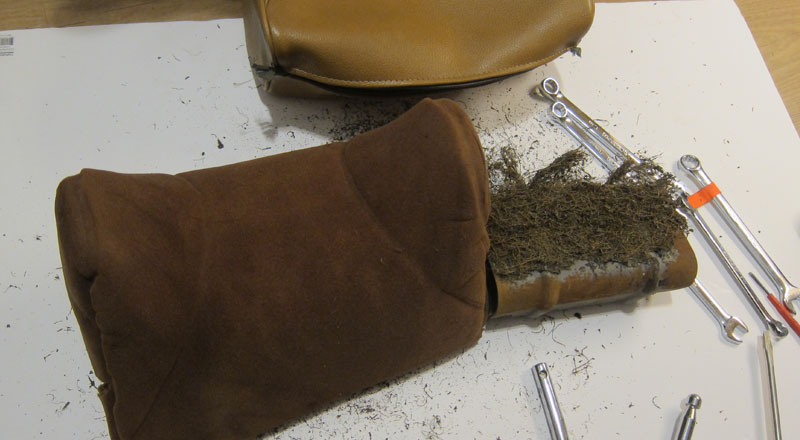
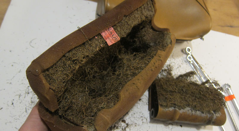
Replacing steering column shifter bushing on your w114 / w115 Mercedes
by Patryk Rebisz
If your column gear selector feels loose, this might mean that your bushings have turned to dust. Follow along to see how to fix it.
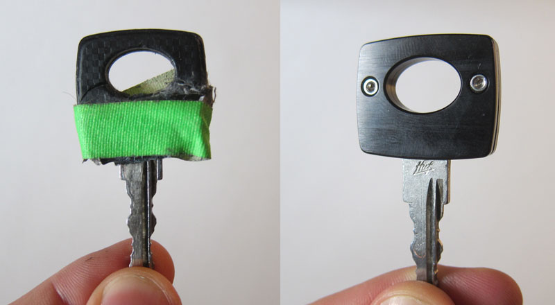
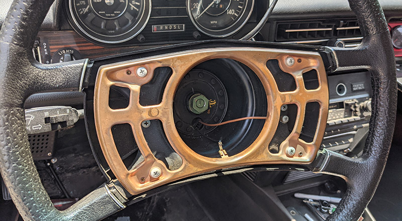
If you have 2nd generation car with rubber pad on your wheel, then you have to pull the rubber edges of the pad to remove it. (It wraps around the cooper metal framing in the picture above on all 4 sides).
Afterwards you will face the steering nut (tightened to 50 nm so be prepared to use some force to undo it). You want to hold the wheel so it doesn't move as you break the nut loose with your wrench. Pull the steering wheel assembly away from the steering shaft.
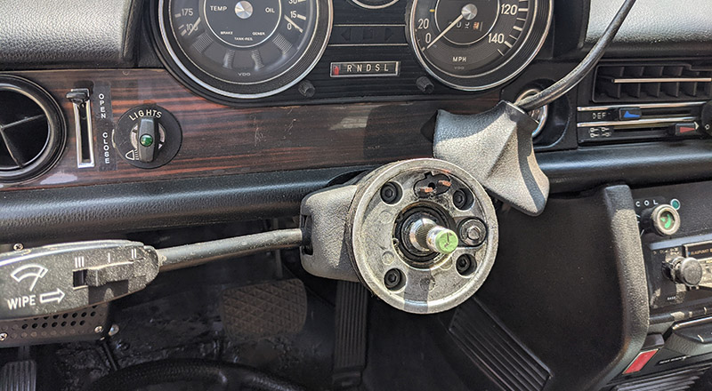
Lift the rubber protective pad of the gear selector and unscrew the plastic holding the selector to the column. Pull away the gear selector assembly. (yellow in the picture)
Pull back the rubber protective cover of the direction indicator and unscrew the two bolts holding the selector to the steering column. Let the direction indicator hang loose (it has a thick set of wires so it will be OK).
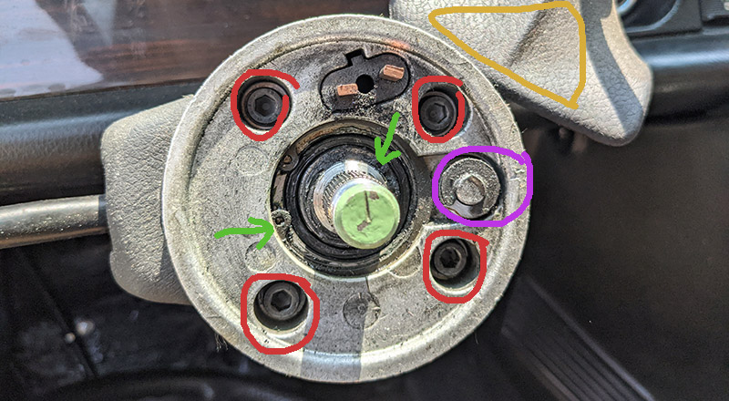
Unscrew the 4 hex bolts from the steering plate (red in the picture) and remove the large circlips in the center (green arrows).
Using pliers turn the gear selector shaft (violet in the picture) 180deg so the circlip faces towards the steering shaft. Remove it. Under this clip there is a bushing (or its remains). There is another same bushing UNDER the silver steering plate.
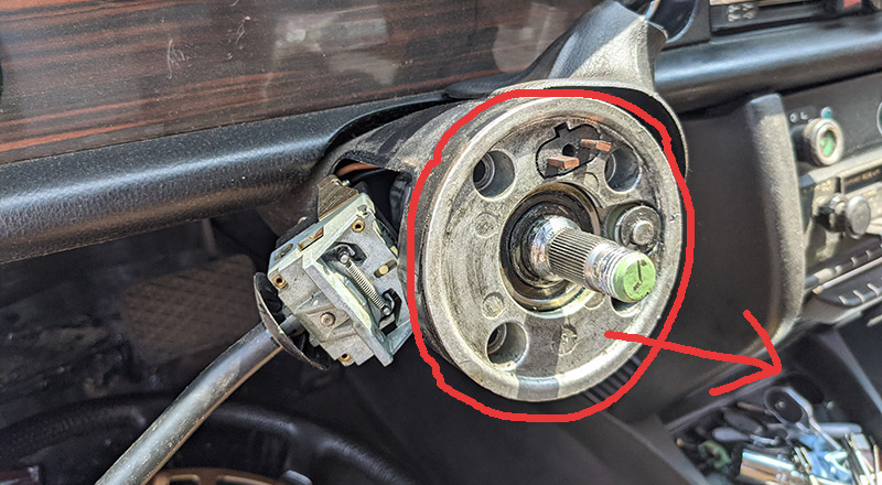
Now it's time to slightly lift the silver steering plate so we can replace the busing under it. The fun begins as it's easier said than done. Temporarily screw on the steering wheel back on the steering shaft and pull the whole assembly towards you. This lifts the aluminum assembly slightly away from the black steering column. Unscrew the steering wheel again. With a flat screwdriver inserted between steering column casing and the aluminum assembly now slightly lifted, carefully pry up the assembly so it lifts around 1inch. Don't remove it all the way as it's still connected to the direction indicator by the horn wires. This should give you plenty of space to clean and replace the selector shaft busing under the aluminum assembly.
Replace 2nd busing on the top of the selection shaft and screw back the whole mess. Done!
What not to do while fixing rust on your car
by Patryk Rebisz
Fixing rust on my 1973 Mercedes revealed two previous rust repairs. One was done decently professional (it lasted almost 10 years), the other very amateurish (lasted 3 years). This helped me to see what works and what doesn't when doing rust repair on your car.
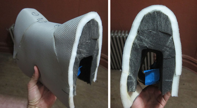
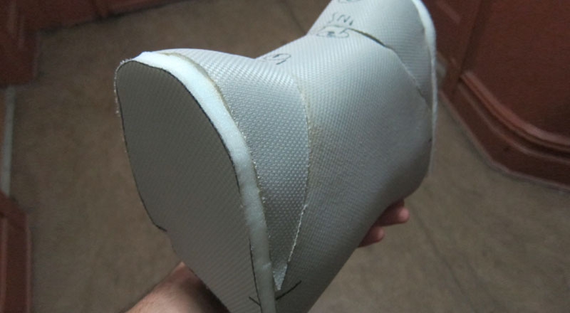
1. Not understanding moisture
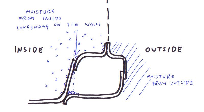
You probably know that rust forms when bare metal is exposed to moisture but probably don't know the moisture doesn't come only from the OUTSIDE of the car. For instance, when it's cold outside and your car's heater is on (see the cross-section of rocker panel above), the moist warm air inside touching the cold metal condenses on the surface. The gravity pulls those moisture droplets down into all sorts of crevices and you have a recipe for rust formation. You have to think about moisture finding its path into crevices outside of the car but also inside.
2. Overlapping the joints too much
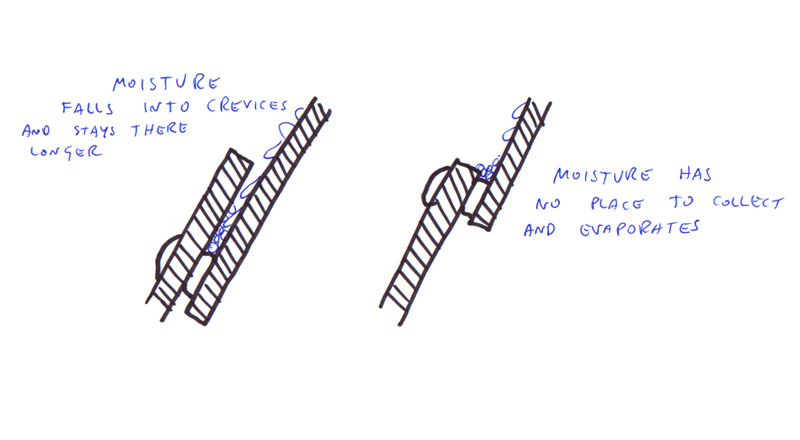
I bet when as young child you played with LEGO you've learned that large overlaps make the structure more sound and solid. Unfortunately, our cars are not made out of plastic but metal and metal has different properties than LEGO's plastic. Besides the obvious differences, metal rusts and so it's imperative to help preserve the car's structure by making the lap joints as small as structurally possible. Why? Overlaps attract moisture and the larger the overlap, the harder it is for this moisture to evaporate.
3. Not wire-brushing welds
When you weld, the joints get covered with all sort of gunk. This gunk must be wire-brushed away so when your put some paint to protect from rust forming, it has good adhesion properties.
4. Not protecting bare metal with paint / Using wrong product as rust-preventive
Let me state it simply: bare metal rusts very easily. It starts flash rusting within days if not hours and can succumb to rust within a year or two. It must be protected by introducing a barrier between metal and the moisture from the air. Paint acts as such barrier. You MUST protect metal in some way or it will rust away.
The paint acts like the easiest barrier material but not all paint is created equal. For example, don't assume that porous primer will save your metal. Its function is to prepare surface for paint adhesion rather than protect the surface from moisture (thus rust). Cover your primer with paint that won't be porous. In general (be ready for a very broad statement), shinny paint tends to create good barrier. This paint, in turn needs to be protected from chipping away. On parts of the car that are exposed to road debris - the car's under-body and the inside of wheel arches - you can apply rubberized undercoating to act as a soft barrier between rocks and the paint. Please understand, rubberized undercoating is somehow porous so it WILL let moisture penetrate to the bare metal if left unprotected. In other words, undercoating on bare metal will lead to rust probably sooner than one anticipates.
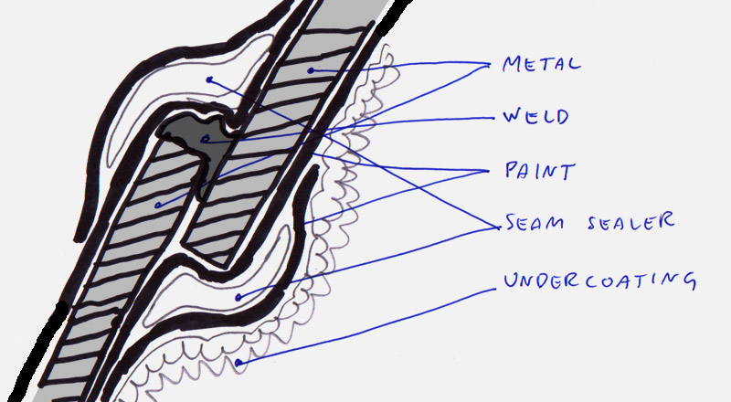
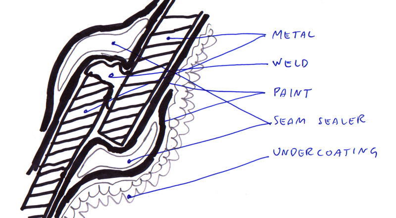
5. Not protecting joint with seam sealer
Your welds are never perfect - especially when you are just starting out - so it's imperative to protect your welds from rusting. After wire-brushing them clean and grinding away excess welding material you should clean your surface with parts cleaner to rid your work of any contaminants, then spray it with paint. When it's all done, seal it with seam sealer so the weld's imperfect surfaces don't create crevices that could trap any moisture.
6. Not preping the edges properly
When you cut metal, the edges are sharp or left with chips. Those small pieces will rust away quickly or hang loose preventing the edges from properly accepting the paint. This, in turn will lead to rust. Moral of the story, polish the cut edges to rid the surface of metal chips and shavings.
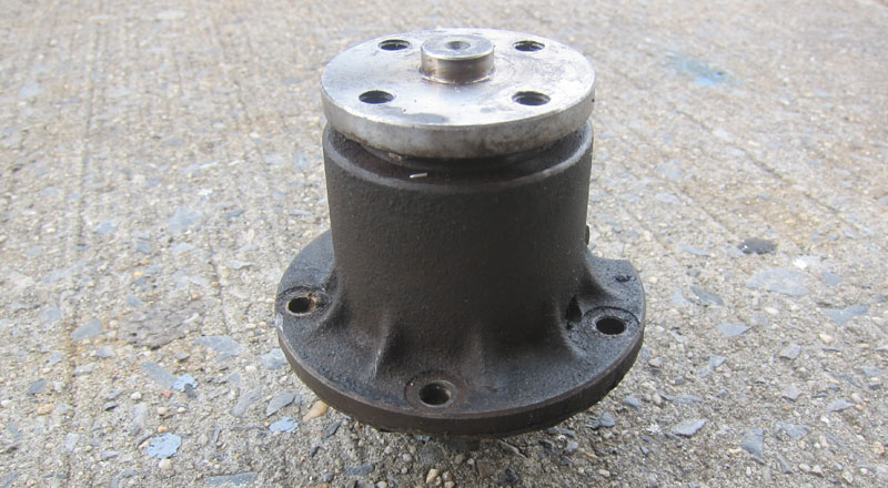
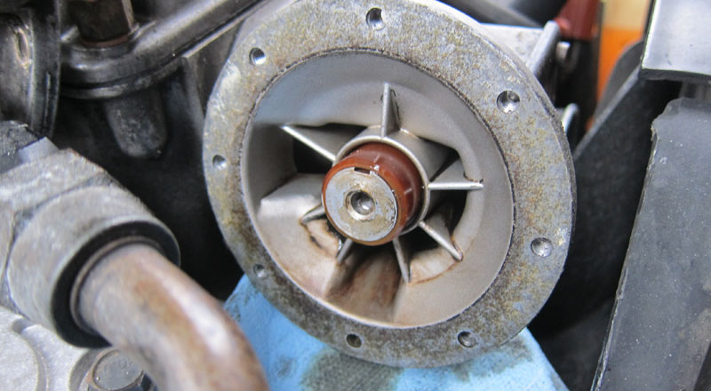
Anatomy of w114/w115 water pump
by Patryk Rebisz
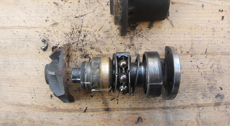
A water pump is a simple device that is spun by engine's power to move water coolant through the engine. In essence it's an impeller sitting on bearings with a "spinner" on one end and a place to attach pulley on the other.
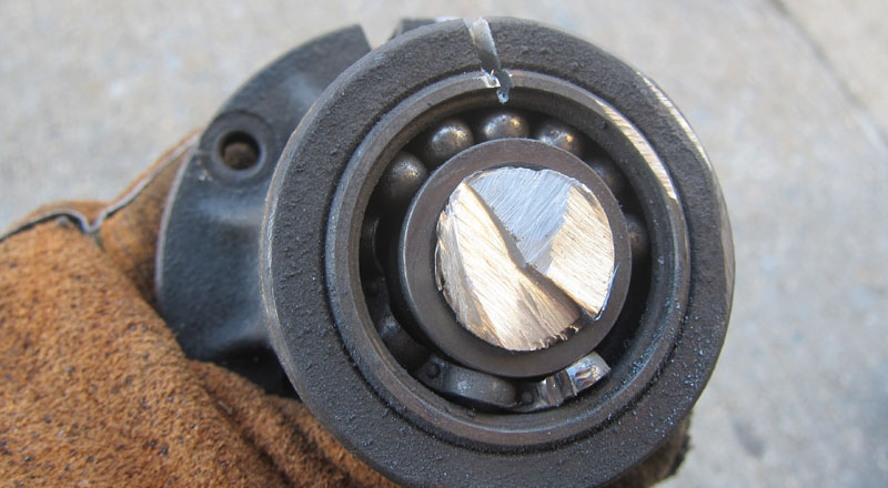
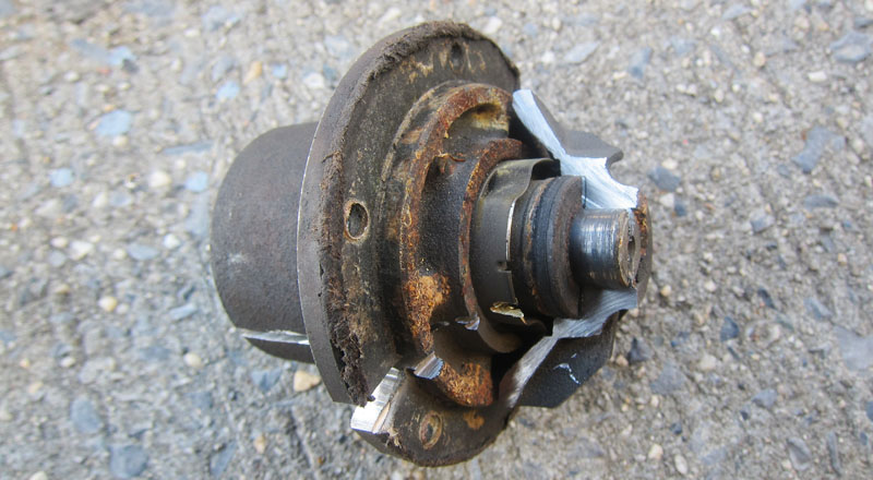
When it goes wrong it can create a havoc. When bearings go, the shaft can start wobbling with fan hitting various engine parts and disintegrating in the process.
How to test if your w114/w115 heater fan indeed is fried
by Patryk Rebisz
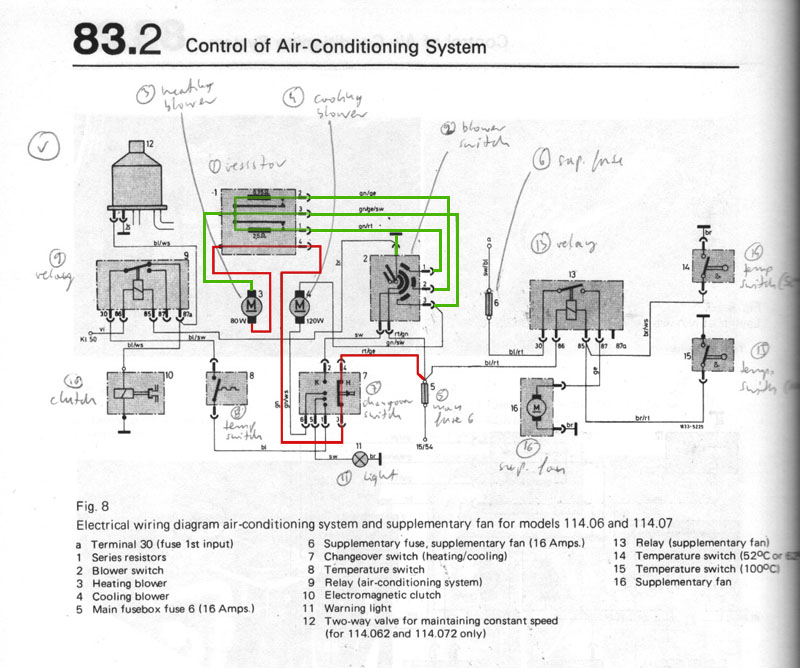
Lets explain the basics. The knob at the center of the vent controls the heater fan's intensity until the AC knob is turned all the way clockwise - then it controls the AC fan's intensity. One fan stops working and another kicks. This causes some confusion as the transformation from one to another is so seamless that some people assume that both fans are still spinning.
The switch happens via a switchover switch near the gas pedal. The vacuum pod extends its rode closing the flap blocking ingress of outside air AND switching the flow of electricity (via the switchover switch) from one fan to another. When things go wrong, assuming the fuses were checked, often its this switch that causes trouble as carbon deposits from arching buildup internally preventing electricity flow.
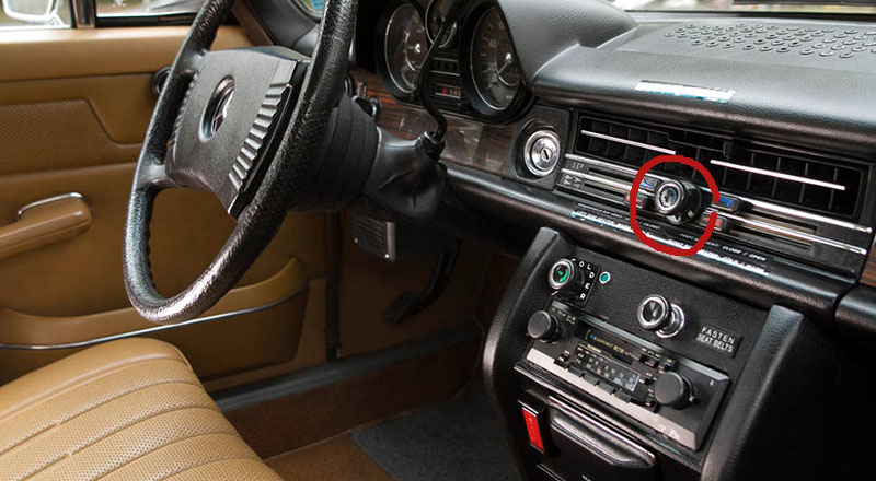
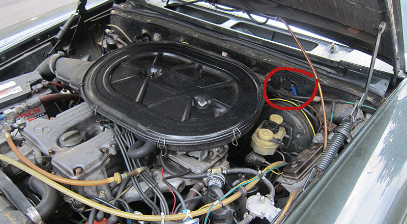
Another problem could be the plug on the firewall that directly feeds the resistor that goes into the fan. Are the contacts corroded? You can test if your fan indeed is dead by feeding electricity directly to the fan bypassing all switches. To do so, first make sure that the fan indeed is spinning by extending a strong, long wire through the interior vent, moving the blades manualy.
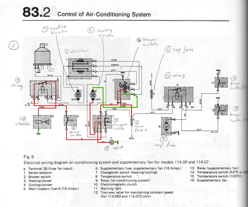
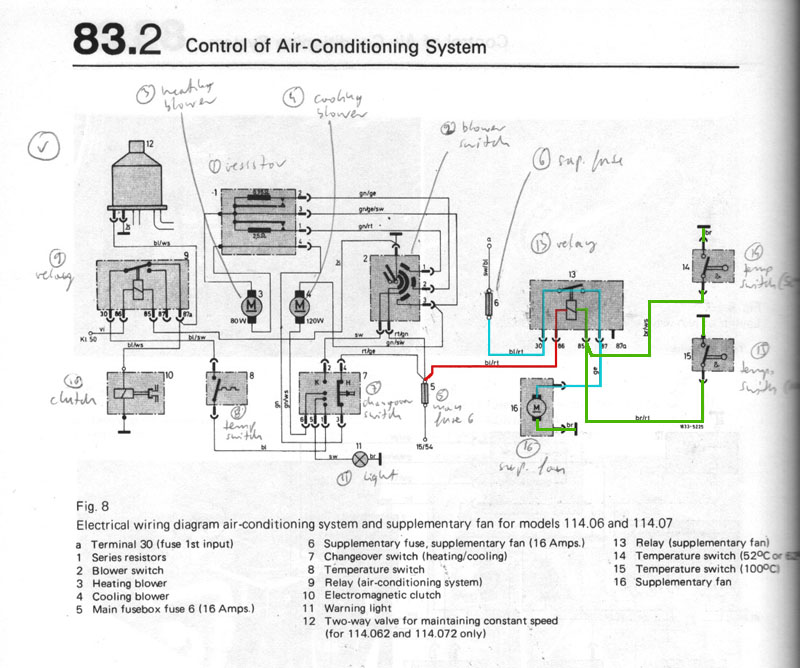
If all goes well, then you can feed electricity through home-made jumper cable directly from the car's battery to the bottom left pin (marked red below). The other wire is grounded to the engine and touching one of the three remaining pins (green below) shall spin the fan at one of the 3 speed settings.
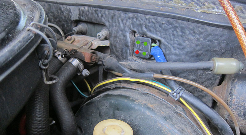
That's it. Hopefully, you won't have to worry about extremely time consuming removal of the center console to get to the fan otherwise!
Basic car metal repair with welding
by Patryk Rebisz
Don't be intimidated by welding as the job is easier then one might imagine. Welding is a process of fusing metal together by using high heat to melt parts together. If done correctly it produces extremely strong bond but because it involves powerful forces of heat produced by electricity, it can be a bit intimidating to a novice. Though sometimes rust can be fixed with fiberglass, there are times when for structural purposes there is no other way than to use metal.
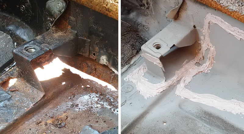
The metal around front right seat support rusted out and this small repair job can be used to explain the steps. Because the support bracket is meant to support the seat, fiberglass repair wasn't an option.
To do the job you need a welder, protective gloves, a mask and a hammer with a point to chip off molted metal overspray. Besides, you also need tools to prep the surface and cut/shape the metal.
1. The problem.
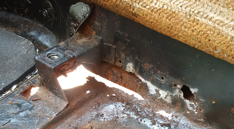
2. Assess the damage. Chip away as much rust as you can to the the extend of rust (it's ALWAYS more than anticipated).
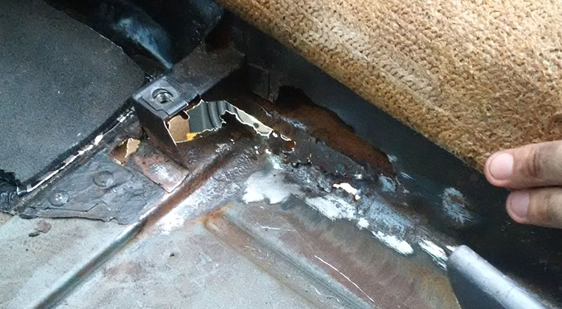
3. Cut out the rusted metal that's too thin to weld to and strip paint around the welding edges.
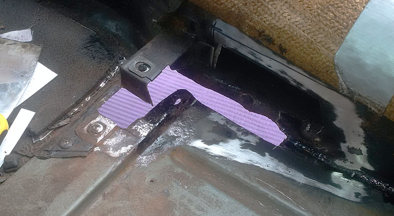
4.Create a template from cardboard for the metal patch; cut and shape the metal patch.
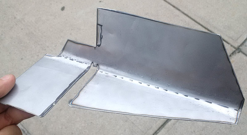
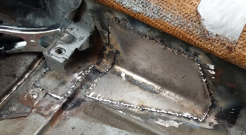
5. Using magnets or temporary metal screws secure the patch to the area then attach ground from your MIG welder to bare metal area. Place the tip with electrode where you want to apply the weld then squeeze its trigger (protecting the eyes from brightness and hands from splatter). Spot weld a few corners to secure the patch in place. Basic welders have very few options - usually it's strength of the electrical current and speed with which the electrode unwinds each time you squeeze the trigger. It's that simple. With some practice you should master the basics in no time.
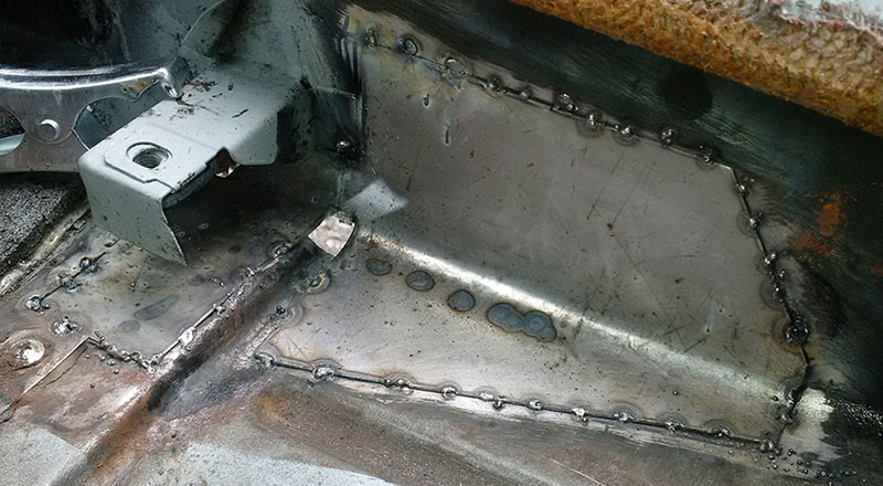
6. Keep on spot welding avoiding prolonged bead of weld to prevent metal deformation.Try to spot away from one naother giving ample time between for material to cool off. When the patch is welded on all sides, grainde off the welds for smooth surface.
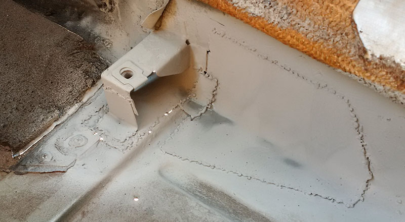
7. Protect the surface of the new metal by painting with some sort of "paint over rust" or "paint with primer." If you don't have access to back of the patch drill access holes and spray wax or rust preventer then seal the access holes with rubber plugs (not pictured).
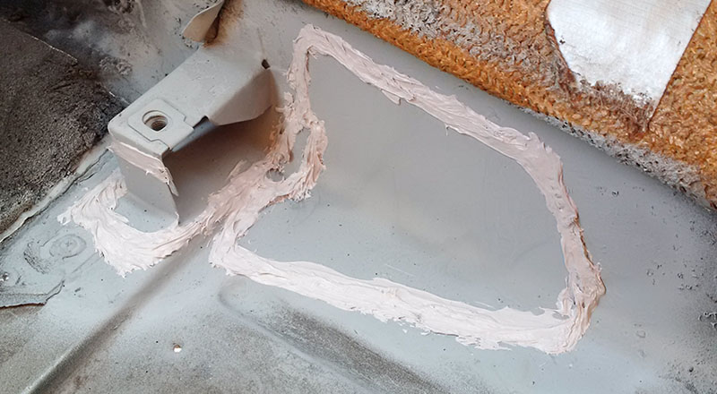
8. For extra weather protection, you might seal the edges with car sealant. Do that especially on the seams facing the outside. Painted and sealed, you shall spray some sort of chip-guard on the outside to prevent the paint from flaking off as the undercarriage is hit by small rocks and road debris.
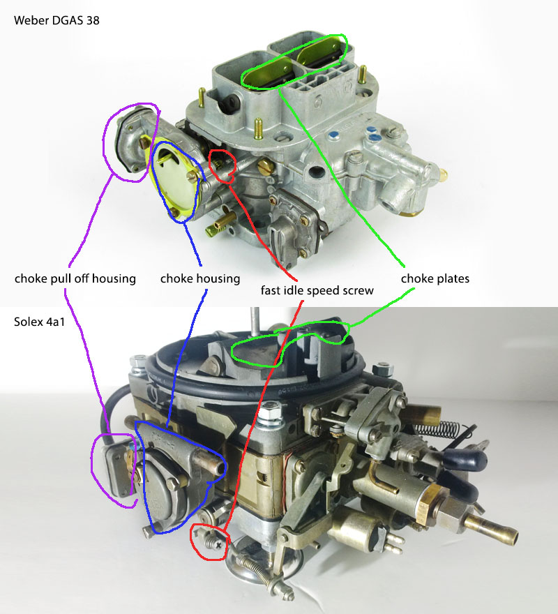
Comparisons of Weber 38 to Solex 4a1
by Patryk Rebisz
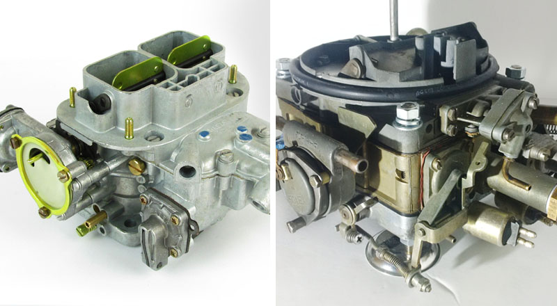
Both carburetors, Weber 38 DGES and Solex 4a1, despite difference in appearance, operate more or less in a similar manner. Fundamental difference between the two is that Weber is 2 throats carburetor while Solex has 4. In regular driving conditions only 2 smaller ones are used and the secondary larger throats open only at higher engine demands. This design lets Solex be more efficient at lower RPMs and still deliver needed power (and fuel) when needed.
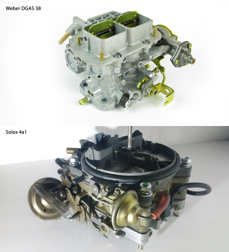
Here are three comparable views of both carburetors.
View 1:
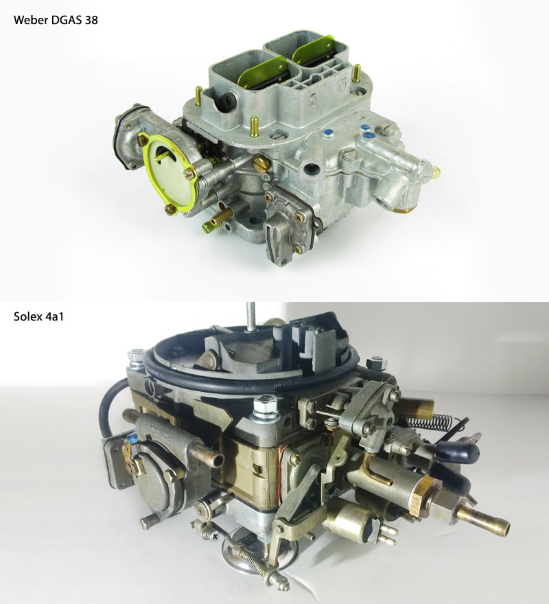
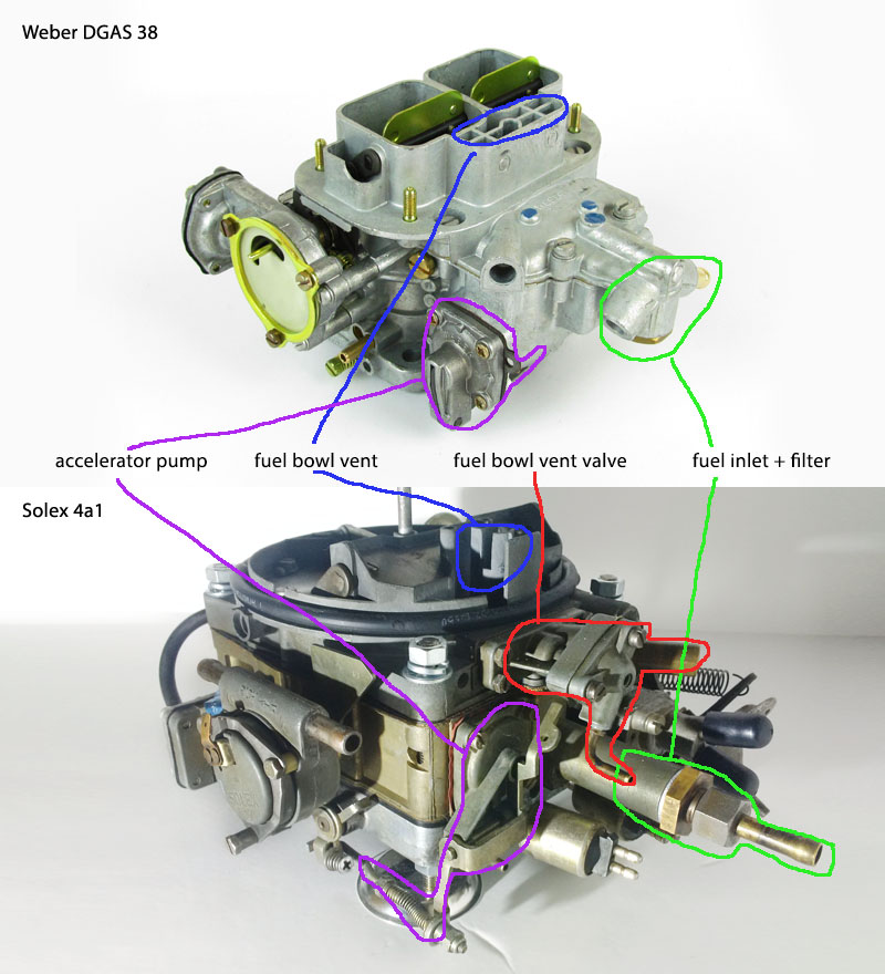
View 2:
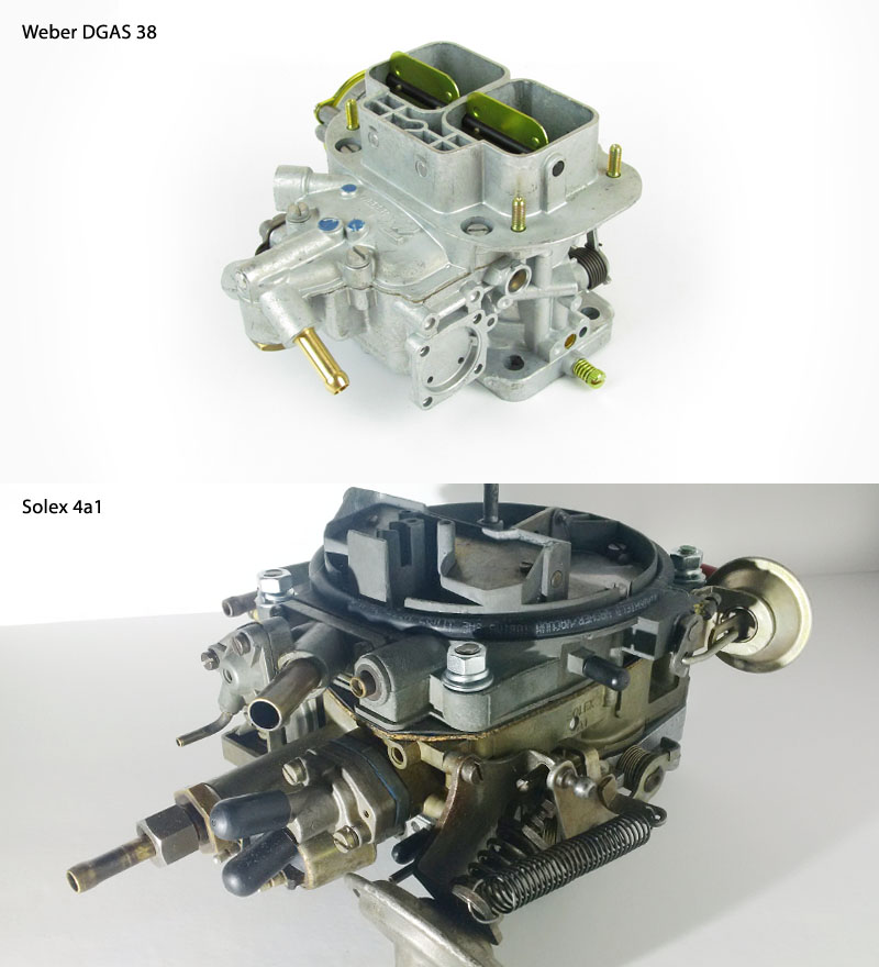
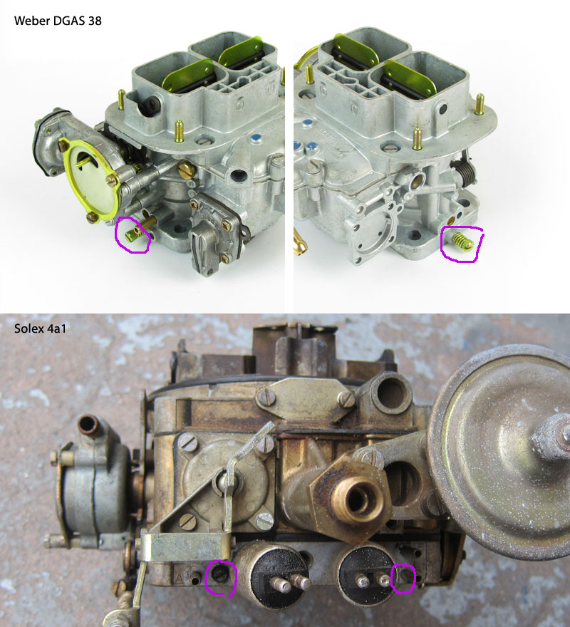
View 3:
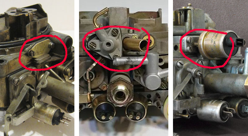
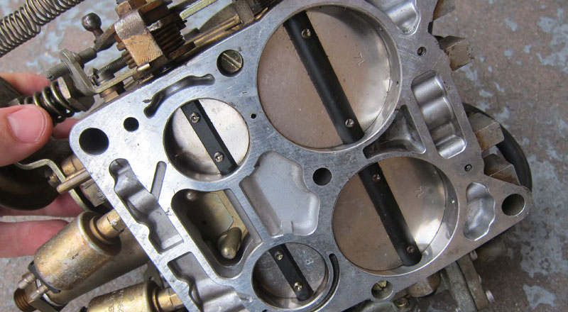
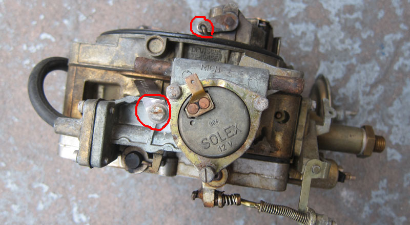
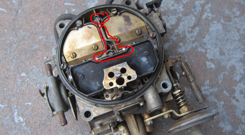
Both carbs have choke plates (to choke the engine when its cold - here in pic below, Weber has the choke plates open while Solex has them closed); choke-pull off (to open the choke slightly immediately after engine starts); choke spring housing (Weber in the pic is missing it while Solex has water-assisted housing attached that require air coolant be flowing through the housing); fast idle speed screw (to hold THROTTLE plates more open when engine is cold and the choke is engaged).
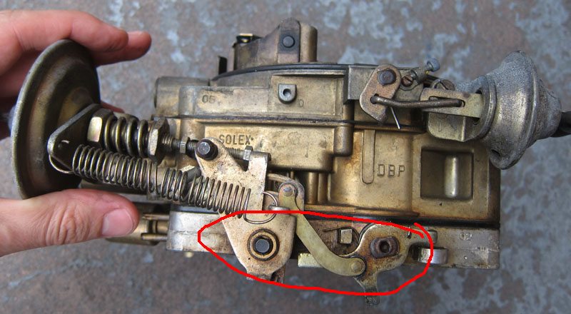
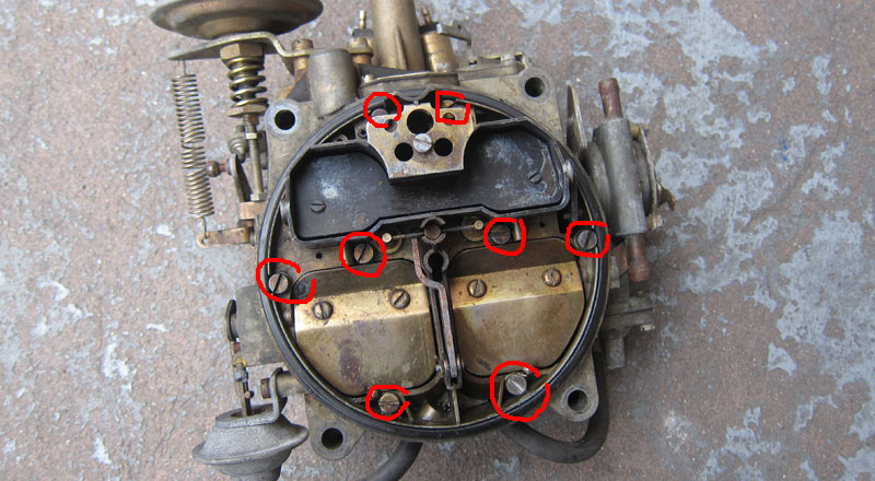
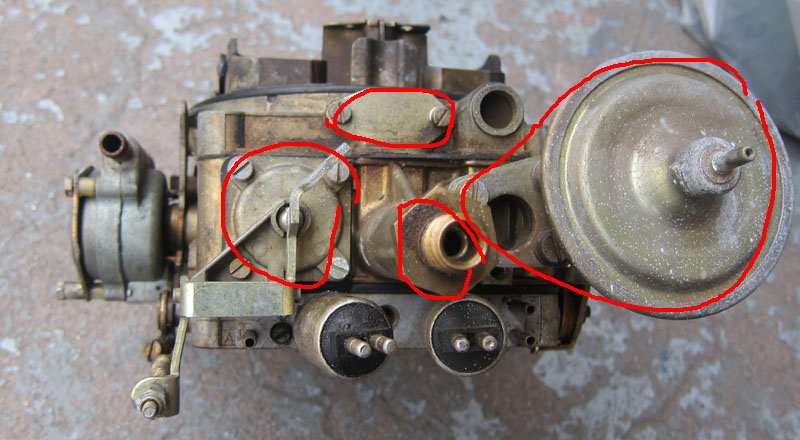
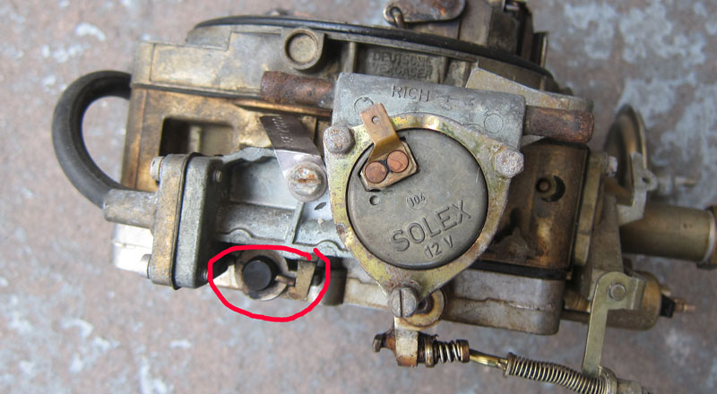
Both (pic below) have accelerator pump (Solex's can be easily adjusted with a screw), internal fuel bowl vent and fuel inlet (Weber's can be re-positioned to face right or left) with filter. In this specific setup Solex also has fuel bowl external vent valve to vent the fuel preventing hard re-start on a hot day. The water-assisted choke heats up Solex way more than Weber so no matter what, in my experience Solex is always a bit harder to start on a hot day than even un-vented Weber.
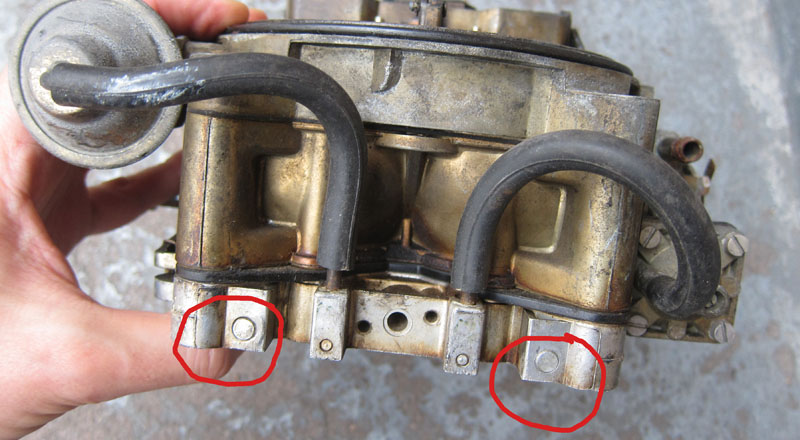
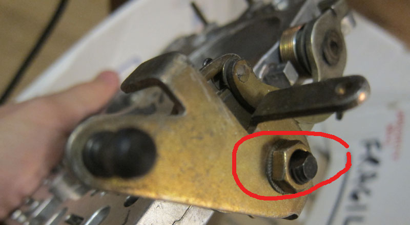
Both have idle speed screws at the base bottom to manipulated how much fuel gets sucked in by each carb throat at idle. NOT, if you are new to carbs, don't confuse idle speed screw with FAST idle speed screw as they have different functions. Idle speed controls RPM when engine is warm, fast idle speed screw controls engine speed when the engine is cold and choke is engaged.
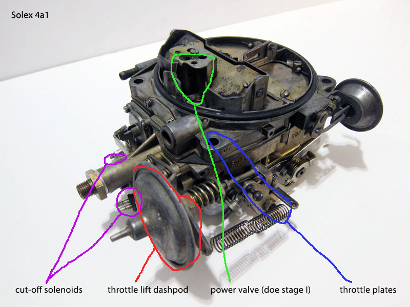
Now onto differences. Solex has more components making it a more sophisticated fuel-delivery device but also more difficult to troubleshoot.
-- TN choke (so the fuel delivery on cold engine can be controlled by a thermostat rather than just a "primitive" spring inside the choke housing - great idea but a huge pain for it to work 45 years later...).
-- Throttle lift dashpod increases idle depending on the engine load, so when you turn on AC that tries to rob you by150 RPMs on stop sign, the dashpot compensates extending its spring and adding the needed extra RPM. This is pretty ingenious device. For this alone you should try to keep your original Solex rather than switching to Weber. If, for whether reason you end up sticking with Weber, to compensate for possible AC's drag on the engine increase your base idle speed by screwing in the idle speed screw.
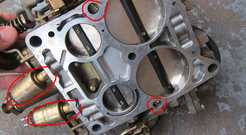
-- Cut-off solenoids.The throttle plates held open by the throttle lift dashpot could lead to diseling of the engine after shut off so designers introduced fuel shutoff devices. On some occasions Weber too can be dieseling if your throttle plates are set to stay more open by the idle speed screw (for instance to compensate for AC as mentioned above). Early Solexes were only internally vented but later on the fuel bowl vent was introduced (at first vacuum operated, then electric).
-- Power valve on Weber is inside the fuel bowl while on Solex it's either on top of the housing or all together missing (as is the case here) as the designers discover it wasn't needed in some applications.
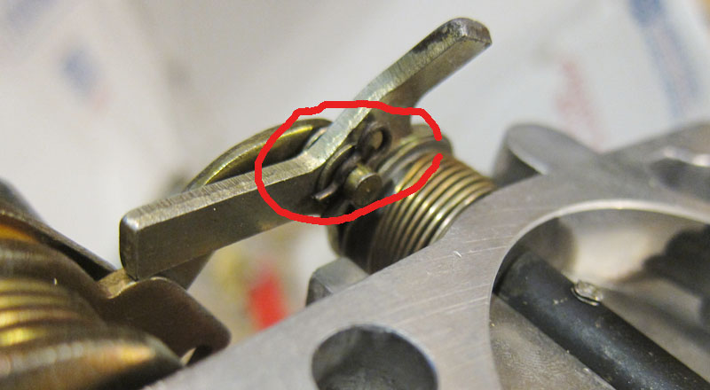
-- The throttle plates on Weber are synchronized by the teethed gears while on Solex they are attached to one continuous shaft. The bolt on the Weber's gears lets one adjust synchronization between the closing of two throats. Even on a new Weber make sure that the gears indeed open throttle plates equally.
The rest of the "extras" on Solex revolve around the II stage that isn't part of Weber's design. Air flaps are NOT chokes- they should stay shut when engine exercises vacuum on the secondaries pod. Secondaries enrichment rods increase fuel intake at higher RPMs. There is a cam on Solex that prevents opening of secondaries before engine fully wartms up to prevent people from pushing engine too far when it osn't ready to give up all its power.
Vacuum pump diaphragms replacement
by Patryk Rebisz
The vacuum pump was installed on US versions and low-compression versions of the M110 engine. It was designed to supplement manifold vacuum, especially under situations related to a panic stop, because Mercedes engineers believed that the intake manifold simply could not produce enough of vacuum, especially at high engine speeds, to supply the brake booster.
Your vacuum pump act as a vacuum amplifier that uses the little vacuum that the intake manifold generates and increases it using a diaphragm type plunger. Sometimes the diaphragm tears. The replacement is relatively easy and if you are the type that wants to know what is involved, here is the break down with pictures.
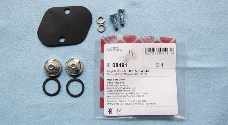
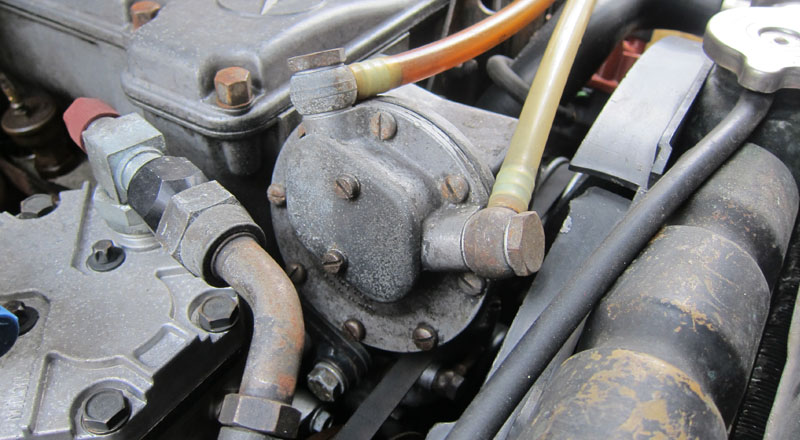
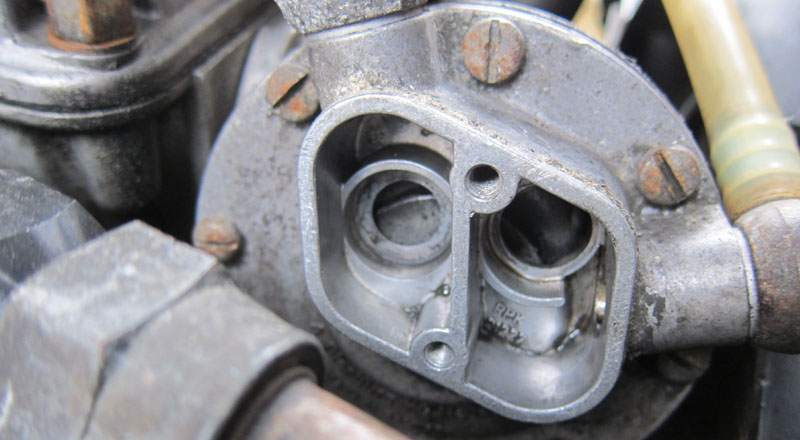
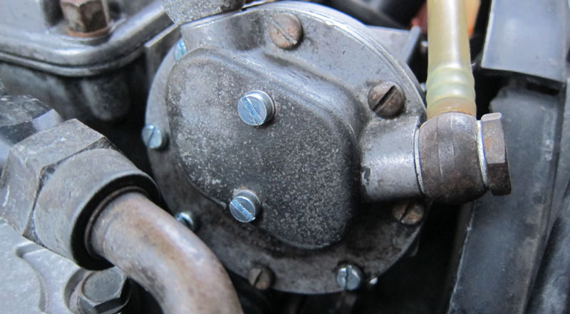
Here is our patient:
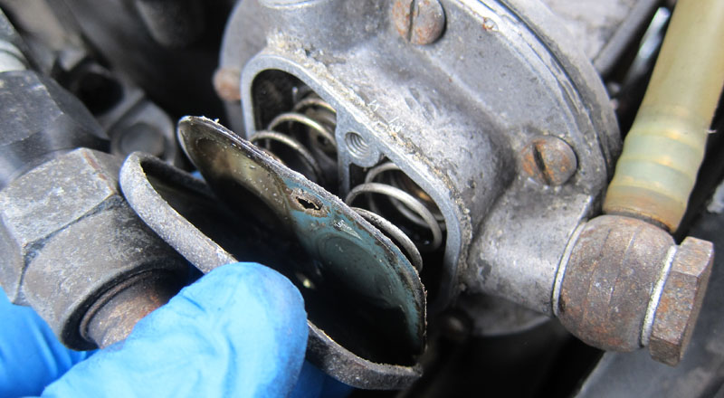
After unscrewing the two screws and a tap on the housing to shake up the seal we find two springs and two valves (notice some oil accumulation):
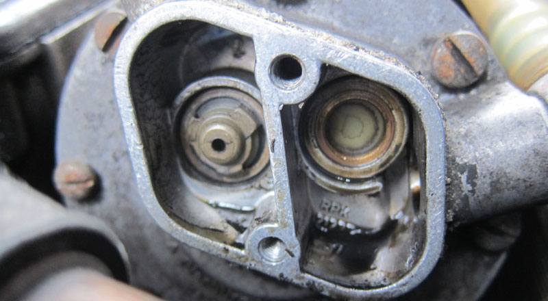
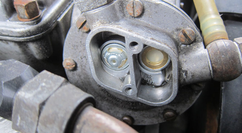
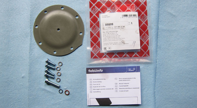
Little clean up and the housing is ready for the new valves from the rebuild kit:
Since this fix is done on a pump still attached to the engine it might be little hard keeping components stay in place. Little synthetic grease will keep the gasket and the valves sticking to the housing. Use the old diaphragm to mark a new one where the springs should touch to help in alignment. Synthetic grease trick is used to keep the new diaphragm sticking to the cover plate then carefully place the springs inside the housing and tighten the two bolts.
Move on to the rubber diaphragm inside the pump itself:
After you unscrew eight screws you might need to use some force to separate the old rubber from the aluminum components. Inside you find this (the rubber mounting screw is already partially unscrewed):
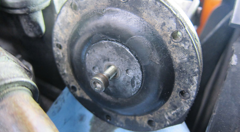
And the piston under the diaphragm:
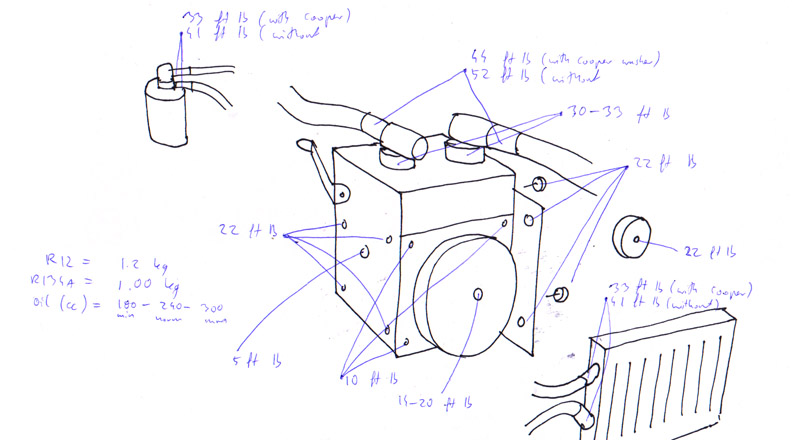
Clean the matting edges of the housing with some fine sand paper then reuse old alan bolt (new one is a few millimiters longer). Put on a cooper washer, then rubber washer, then metal disk, then rubber, then larger metal disk. Make sure the metal disks face the round sides towards the rubber.
Carefully tighten the alan bolt (put some blue locktite on it) making sure the rubber holes align with the housing the screw in the housing - notice how for whatever reason they only provide 4 replacement bolts.
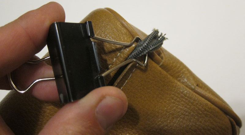
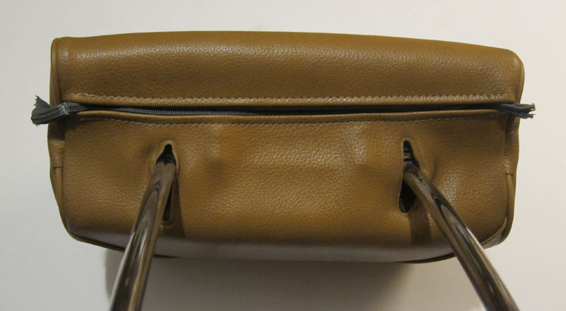
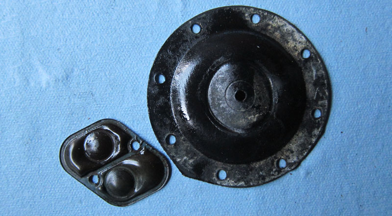
As a bonus, here is what old diaphragms looked like:
Difference between your car's cold and hot air intake
by Patryk Rebisz
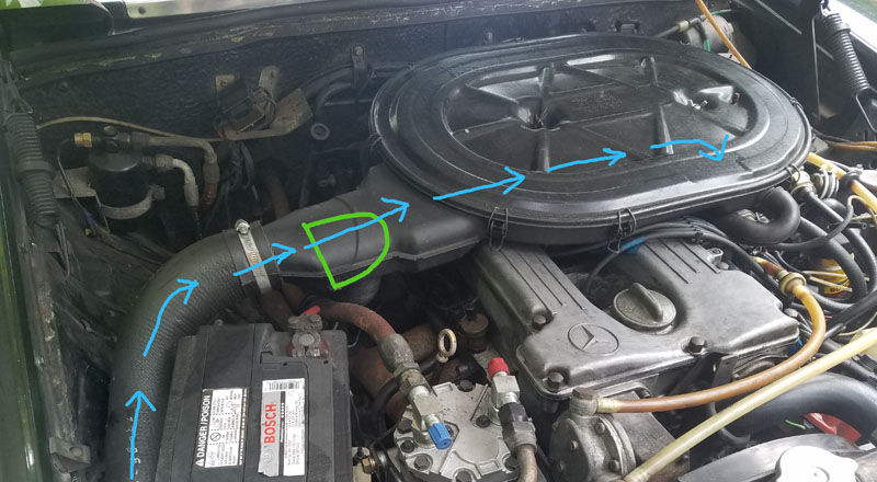
Your air cleaner is connected by some insulated hose to the cold air inlet. With time that hose deteriorates and people just remove it inadvertently taking away power from their cars. Why? Because cold air is much denser than hot air thus carrying more oxygen molecules to burn up in the engine.
Most vintage cars have hot air raiser (green flap in the picture below rerouting air) which serves to warm up the air through the exhaust manifold that, in case it wasn't obvious, heats up very quickly - often within a few seconds after engine's start, it can be too hot to touch. The principle here is to warm up the carburetor and the intake manifold as quickly as possible. At this stage, the performance that comes from cold (thus denser air) is traded for warm air so the engine internals warm up enough to stop condensing the fuel/air mist on its internals because the mixture that drops out of evaporation is that much harder to ignite.
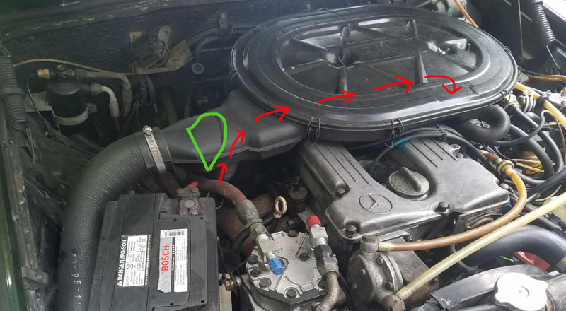
After the internals warm up enough, the heat raiser closes (the flap is control by some sort of thermostat) so only cold air is let into the intake.
The difference in performance? On a typical 70F (21C) day, air density is 1.2 kg/m3 but at 140F (60C) it's air density drops to 1.06 kg/m3. That's a 13% drop! Of course, you can't automatically make the assumption that your engine performance increases with cold air by that 13% as other factors come into play, but those figures should point out that if your air filter design calls for an air hose - it has its purpose. Likewise if your thermostat is broken or your airflap hangs loose, you might want to fix it bringing it back to the manufacturer's specs.
Solex 4a1 carburetor re-build
by Patryk Rebisz
Before taking your Solex 4a1 carburetor apart, evaluate your "patient" and prepare yourself understanding that a re-build is not as simple as swapping some gaskets. Your 40+ year old carburetor will most likely have a number of issues that need to be solved before you can call your re-build a success.
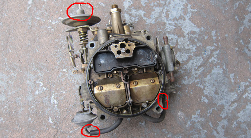
You should check all the exterior components to see if you need to source those from some place as it isn't uncommon that at least one of those failed. Using an inexpensive vacuum pump see if the air dampener, throttle lift, and the choke pull off holds vacuum (pic below).
If your air dampener isn't holding vacuum, your secondaries air flaps will open way too easily extremely leaning out the mixture creating a very erratic driving experience (you might be able to source one from a place that provides spares for Quadrajet carbs). The only way out of this dilemma, short of getting replacement part, is to wire the secondaries shut (in essence disabling your high RPM power potential) - then you might as well just swap your carb for a Weber.
If your throttle lift doesn't hold vacuum - the constantly extended spring will significantly increase your idle. If the can isn't working, just screw in the screw so that it won't have any effect on your idle. This will decrease your driving pleasure as the purpose behind the throttle lift is to increase idle throttle when the engine is low on vacuum due to increased demands such as when your AC is on.
If your choke pull off doesn't hold vacuum (it's OK as the rubber diaphragm on all but very earliest models come in the rebuild kit), when the engine starts the diaphragm will not slightly open the choke, flooding the engine.
When you have the pump out, also check the can in the fuel pressure regulator (not pictured here but it's the can right before the fuel inlet). If it isn't holding vacuum, the fuel might be pulled through ripped diaphragm into the intake manifold greatly enriching the mixture. This part is not easy to find, but if yours isn't working, with some ingenuity, you should be able to use a replacement from another manufacturer.
Also test the fuel vent, if your carb has one (not present here, but see the options in the picture below). It needs to operate when vacuum (or electrical current, depending on version) is applied otherwise your fuel consumption and drivability will suffer. The diaphragm doesn't come with the re-build kit.
If all those components check out, move on to the shafts of the air horn. See if the choke plate opens freely (you might want to disconnect the cam holding it down), likewise see if secondaries air flaps open and close without binding. They are held up by spring tension so most likely it will spring back up when you press it. If the spring is broken (some kits come the replacement, but most don't), the flaps will just hang down but they should still move freely without binding. When the air horn is tightened too far, those shafts bind against distorted housing and then you must ram out the shaft holes for smooth operation (I don't cover this part, because it happens relatively infrequently).
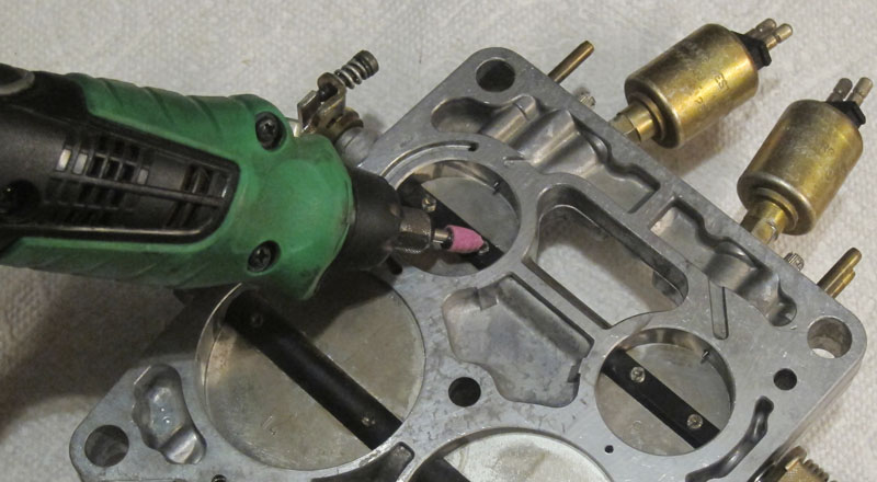
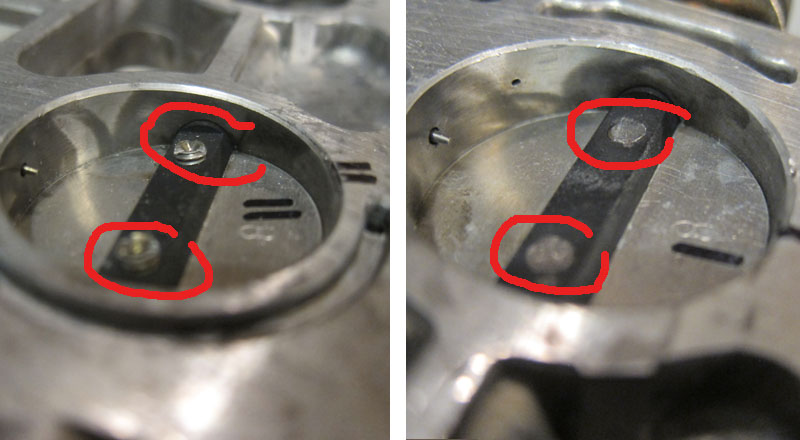
Your throttle shafts almost certainly might need new bushings. Turn the carb on its back and see how much play you get in the throttle plates. Side-to-side play is OK but any up-down or back-forth, indicating that the holes holding the shaft are not round anymore, is not. This will cause vacuum leaks and the imprecise throttle openings often delivering a different fuel mixture to one side of the engine versus another. One of the tell-tell signs is the discoloration around the throttle shafts indicating fuel sipping out (pic two below). If there is any play, you most likely will have to re-bush your plate. Mechanical parts wear out - this is just part of the game. Primary shaft is 8mm (use 5/16 reamer for bushing then just rim it down to 8mm) while secondary is 10mm (use 7/16 reamer for bushing then just rim it down to 8mm). (read more about re-bushing)
You also have to ask yourself what you will do about the TN choke as it might be stuck open or closed upsetting the fuel/air mixture. The very early Solex carbs (such as this one in pictures) didn't have that device so if yours isn't working, just find a way to disable it remembering that in open position it will crate a vacuum leak. Understand that over the years there were many variations of the basic Solex 4a1 carburetor - all with small modifications to the carb's body components. You can identify some changes by looking at the fuel bowl vent (from none, to vacuum operated and ending up with electrical - see one of the pics above), presence of TN choke and the sort of choke pull off. The manual for the carb is 180 pages, so don't automatically expect that the pieces are interchangeable. That said, the chokes, air dampener and throttle lift cans change from one carb to another easily so getting a spare used carbs with those components working will greatly help in your rebuild.
Now that you know what to expect and still decided to go DIT route, get ready to take your carb apart. Needless to say, take lots of pictures to help you with reassembly.
Disassemble steps:
1. Use copious amounts of carb cleaner to wash the body.
2. Remove the pin holding the choke and force the choke cam off the linkage. Remove the screw holding the choke housing and set it aside along with the cam holding secondaries shut and the choke level.
3. Remove another pin holding the secondaries cam and rods and pull the enrichment device out.
4. Remove the top screws (8 in total) and pry top air horn off the body. Both parts will most likely be stuck so use some force but also be gentle!
5. Remove the bottom screws (2) and separate body from bottom plate twisting it around from the accelerator pump linkage. Unscrew the idle mixture screws and the fuel shut off valves.
Applying 12v current see if their tops open and close (you will also hear a click). They barely ever fail but if yours do, you might want to simply block off the openings with some short screws (short enough so they don' block the passage) as the shut off valves are not crucial for carb's operation.
6. There are a number of screws that should never be touched because those were set at the factory but, of course, many were molested by "mechanics" over the years. The air bypass screws at the carb's base (bless you if yours are still plugged as in the pic below) control how much extra air is pulled in by the engine on carb's each side. If your were adjusted, you need to balance the air flow on both sides. You can do so by constructing a crude vacuum measuring instrument as outlined here.
7. Unscrew the remaining accessories from the carb's body: accelerator pump, fuel vent (or the plate as is the case here), throttle lift and the fuel filter.
8. Open the choke housing by unscrewing the 3 screws on the side and 4 screws on the back removing the rubber diaphragm. Also remove the acceleration pump from the carb's front.
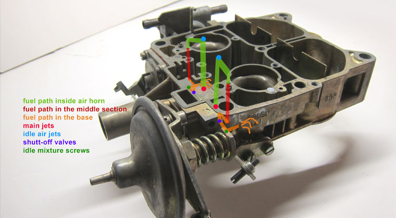
9. Using a metal edge check which parts of your carb are warped. Those carbs are prone to heat induced warping. Let me rephrase - they all are warped to some extends (four Solex 4a1 carbs I have all exhibit this issue). The warping introduce vacuum leaks causing very rough idle as fuel is pulled through two gaskets (see the pic below) so if any of those passages isn't tight and there is a vacuum leak, the air instead of fuel is pulled into the engine upsetting your perfect mixture balance.
What to do if your carb is warped? Well, first see how bad it is by placing a straight edge to the bottom of top air horn in a number of areas. Estimate the largest gap. The thickest gasket material you can buy is 1/16in (around 2mm), so if the gap is larger - you are out of luck as far as this write up is concerned. However if the gap you find is small, read on. Also understand that the typical gasket thickness from a rebuild kit is only 1/32 (around 1mm) so almost certainly you will have to create your own gasket out of thicker material. You might get away with gluing two gaskets together to create one thicker one but as you know you technically shouldn't do that as it might induce leaks. The idea here is to slowly keep on tightening the air horn to the fuel bowl section compressing your thick gasket until all gaps are filled.
Bottom plate is most likely straight as if the bottom side of the body section. The body and air horn is most likely warped. To compensate, you might need to cut out a thicker gaskets (read about it here).
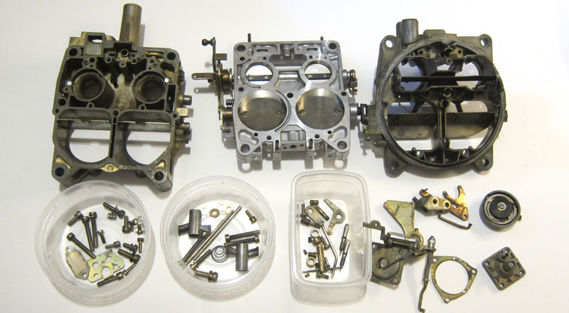
10. You should now have your carb in 3 main pieces and a bunch of smaller elements. Clean all the passages with a healthy dose of carb cleaner (wear eye protection!!!), old toothbrush and soft cooper wire to unclog all passages, then blow it out with compressed air. For caked over carbon/oil deposit you can use Sea Foam.
At this time you can confirm your jets if they are correct for your carb and year.
1973/74 Federal: main 100, air 110, 2nd stage A4, choke 80/89 (1973) or 104 (1974)
1974 California: main 112.5, air 100, 2nd stage A5, choke 103
1975/76 Federal: main 100 (1975) or 105 (1976), air 102.4, 2nd stage A7, choke 89
11. Confirm that your primary boosters are tight and if not re-stake those (mine were loose).
12. Using vacuume pump, check that the fuel bowl needle and seat is holding vacuum.
Time to screw the carb back together. You should have your bottom plate re-bushed (read here), your new thicker gaskets cut out (read here), and your malfunctioning parts replaced. You should also have your re-build kit on hand.
Re-assemble steps (pics are coming soon):
1. Replace rubber choke pull off in the choke housing. You might have to sandpaper (user very smooth grit) the surfaces for more exact fit especially because over the years even aluminum rusts so the edges might not be smooth anymore introducing a vacuum leak.
2. Replace rubber washers on the idle screws and the shut-off valves.
3. Replace rubber for accelerator pump.
4. Replace the metal ring for the fuel inlet after inspecting that the filter is clean.
5. Replace the fuel bowl plate/vent gasket.
6. Replace the fuel needle and reassemble the float with pin and spring. This is a good time to set the float height (see basic Solex carb set-up).
7. Re-attach the choke with cam and the lock cam.
8. Grease up the bottom gasket and assemble bottom and middle part with the 2 screws. Grease helps the gaskets not to stick to the surfaces.
9. Grease up the top gasket and assemble middle section with the air horn. Make sure to insert the choke cam carefully into the top section. Screw in the 8 screws.
10. Attach the secondaries rod and lifter cam.
11. Attach whatever else there might be.
Final Notes:
A professional rebuild costs anywhere between $450-800. At first the prices might appear outrageous but if you conciser all that will get done, you might want to rethink your initial sticker shock.
Solex 4a1 - how to deal with warping
by Patryk Rebisz
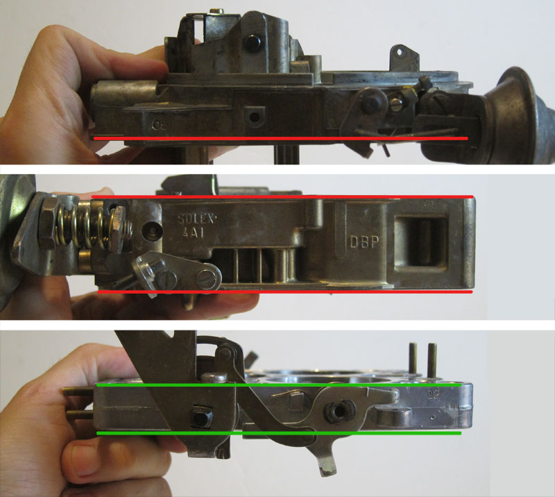
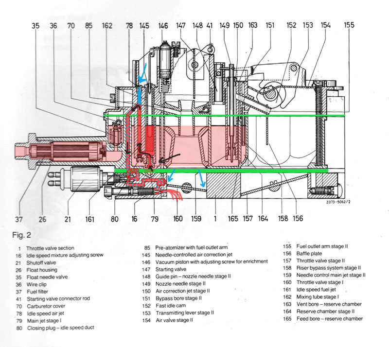
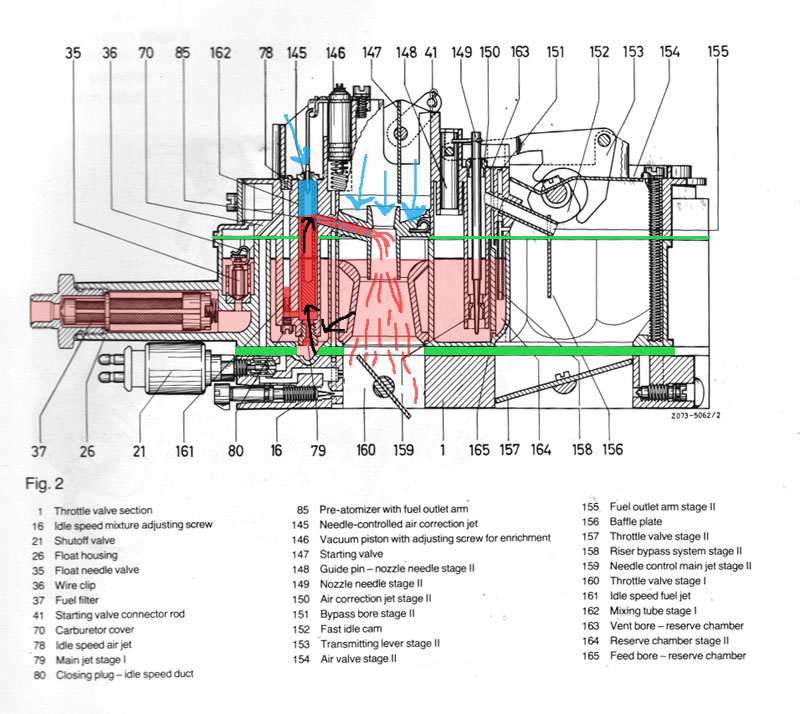
Solex 4a1 carburetor warps. Period. There is no way to avoid it. What differs between each particular carburetor is the amount of that bend. If you take a straight edge to each of carb's 3 parts, you will find that the top and bottom edge of the base plate remains consistently flat (green lines in pic above). It's the other two parts - the middle section and the air horn - that warp (red lines). The cause of that warpage is over tightening of the carb corner mounting lugs AND over tightening of the nut holding the air cleaner. The first action compresses the edges down, while the second pulls middle section of both mid and air horn up. The flat surfaces loose their air tightness and vacuum leaks develop resulting in a poor idle and driveability.
This problem isn't helped by the fact that the gaskets in the rebuild kits are very thin (1/32in or 0.7mm), as if they were meant to simply replace old gaskets in a NEW carb. In reality, you can deal with the warpage by incorporating a thicker gasket that unfortunately you will have to cut out yourself from a thicker material. I use 1.6mm (or 1/16) Fel-Pro 3187 gasket material to merge air horn to mid section, and Fel-Pro 1/32 (0.7mm) as top layer for the plastic spacer between base plate and mid section.
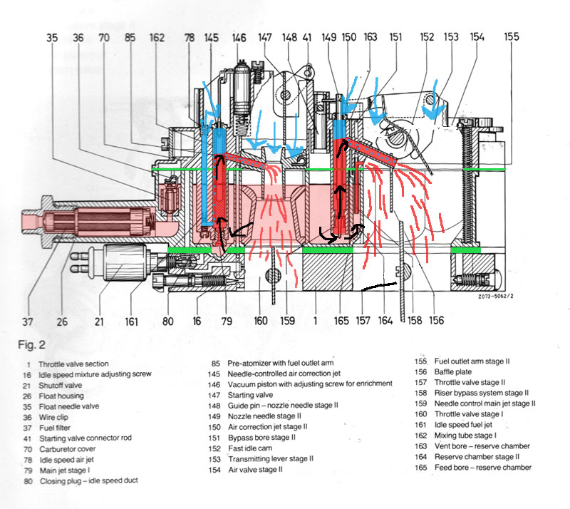
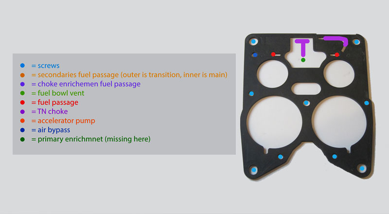
The top gasket (pic below) between air horn and mid section is intricate, so it helps to know what the passages are for so that if your re-build doesn't need certain detail you can omit those.
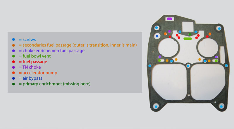
For example, see how those two gaskets below differ. I omitted a number of unnecessary passages for components that are not present on my carb version (there were numerous modifications over the years - read about it here) such as TN choke, TN choke enrichment, primary enrichment and stiffened some outlines that would make cutting the gasket that much more difficult:
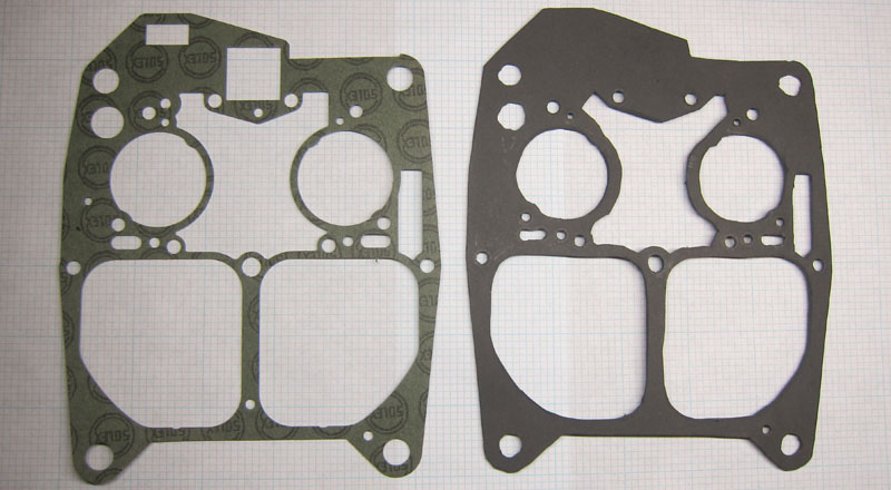
Here is the bottom gasket:
If you wnat to understand why those openings exist in the first place, have a look at this series of diagrams here. If you are patient and careful, you will have quality gaskets that will seal the passages. All you need is some scissors, sharp scalpel, and a hole puncher with interchangeable bits. Cover the new gaskets with some lithium grease to prevent it from sticking to the matting surfaces then carefully tighten the screws.
Be aware that by thickening the bottom gasket you will have to grind down slightly the locking cam that prevents secondaries from opening until the engine warms up.
Done!
Please be aware that just replacing your gaskets might not fix your carburetor. You might need throttle plate re-bushed (read about it here), and there might be other sources of vacuum leaks.
Solex 4a1 carburetor re-bushing (primary side)
by Patryk Rebisz
Machines wear down - this is a fact of life. When two metal parts touch, such as throttle shaft against carburetor body, they wears down unless a thin film of oil is provided. As gasoline is a strong dissolver, oil in that environment doesn't stand much chance so in no time you will end up with meta-against-metal friction. A machine that is 45 years old will show signs of age. Examining any old carburetor you should see the extremity of the throttle shaft wobble against the carb's body. Of the four Solex 4a1 carbs I have - ALL had some sort of throttle shaft play.
Why, you might ask, is it important to fix the wobble with re-bushing? Two reasons. The wobble means that the shaft isn't rotating inside a around hole, rather in an oval. This might introduce extra air into the intake chamber - in essence creating a vacuum leak. Moreover, understand that carburetor at idle and off idle is a precision device with pinhole-sized openings for fuel. Any offset in that precise control of the throttle shaft will have negative impact on your car's idle as one side of the carburetor will takes in a different volume of air than the other side.
The re-bushing isn't difficult but it isn't for the faint of heart either as you might ruin your base plate. Even though there are many places that can re-bush Quadrajet carburetor (very similar to Solex), they don't touch our carburetor or if they do, their prices are extravagant (a few hundred dollars and up). So your own rebushing might be the only answer.
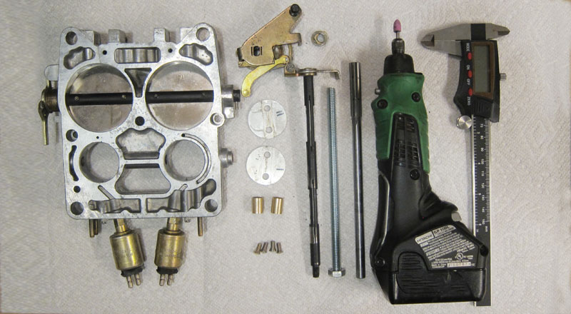
To re-bush your Solex 4a1 carburetor, you will need the following tools:
-- 5/16 reamer around 7" in total length (you can get a generic crappy version that will last for 1 or 2 reams from this place; the kit comes with some bushings too but they are crap)
-- 5/16 bronze bushings (from here)
-- 8mm reamer (ebay)
-- two 5/16 long bolt around 6" in length - one with top cut off (local hardware store)
-- red locktite (local hardware store)
Other tools:
-- measuring calipers
-- drill
Procedure:
1. Mark the throttle plates directions so later you can insert the plates in exact same position.
2. Grain down the stacked screws holding the throttle plates. Unscrew the screws and pull the plates out. If you don't, you might damaged the throttle shaft trying to unscrew the plate. Save those screws as you will re-use them later.
3. Pull out the pin holding the throttle level to the secondaries shaft.
4. Unbolt the nut and using WD40 as lubricant on the shaft, pull out teh whole assembly of the primary throttle spring. You can pull the throttle shaft out.
5. Using your new bronze bushings as guide, mark on the reamer how deep you will want to drill. You want to make sure NOT to drill into the throat chambers so the plates close fully.
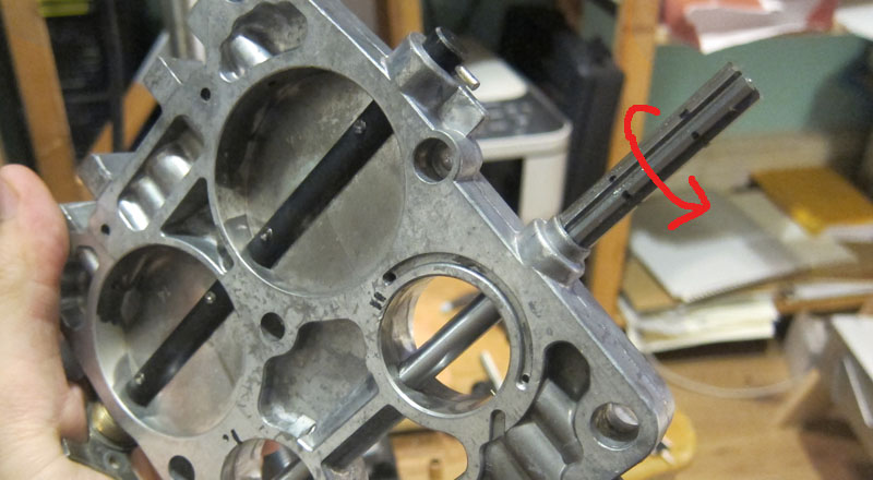
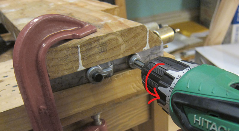
6. Mount the reamer part in drill's chuck so that the smooth part of the reamer will act as guide in the carburetor's base. Remember that in this configuration you need to set your drill to spin counter-clockwise to cut. With firm pressure cut out the placeholders for new bushings. Remember not to cut too deeply - stop on the mark!
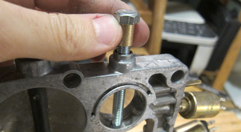
7. Put a small drop of red locktite (not in the picture) on the bronze bushings then insert the bushing around the 5/16 bolt. The long bolt will be used to guide the bushing so it sets in centered. Tap the bushing in and let the locktite cure overnight.
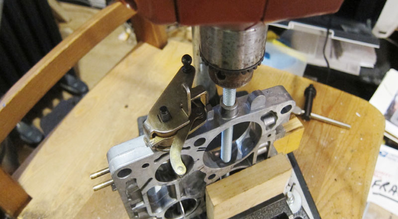
8. At this stage you have a bushing installed with 5/16 opening. The opening is around 7.80mm while your shaft is around 7.95. You will need to enlarge the opening with 8mm reamer to cut out extra material from inside of the bronze bushing. This part gets a bit complicated because the shaft of the 8mm reamer is too thin to use the alignmnet technique from point no 6. Instead, I used 6in long 5/16 bolt with its head cut off in my drill press to align the plate (pic below) then replaced the bolt with the 8mm reamer to enlarge the hole.
9. Insert the throttle shaft making sure it doesn't bind and moves freely.
10. Reinstall throttle plates and tighten (don't use locktite yet). Make sure everything is smooth and that throttle plates sit snugly agains the carb body. Slowly open the plates looking at the transfer holes. Are the holes exposed equally in both barrels? Only when you are happy with the results unscrew one screw at the time and use red locktite for final assembly.
11. Reinstall the throttle lever, washers and pin. Done!
You can use the same procedure to replace the secondaries throttle
shaft. The only difference is in bushing size (3/8in) as the reamer for the bushing hole for the secondaries shaft if 10mm.
|