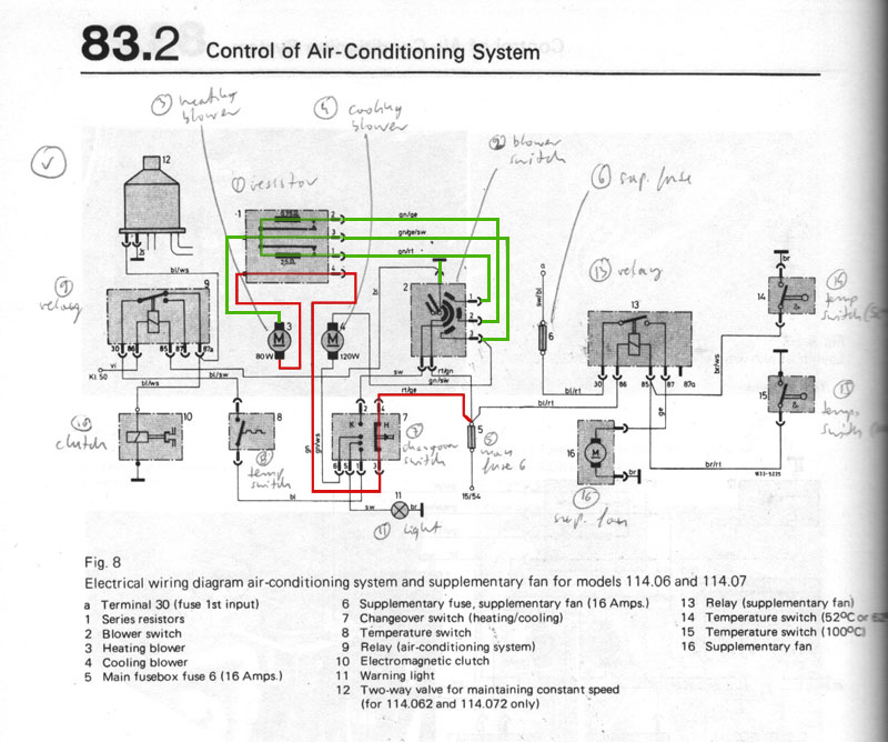
To power heater fan:
Through main fuse (5), power (in red) is provided to the changeover switch (7). From there the power moves through resistor (1) and to heater fan. The circuit is closed (ground in green) when you turn the heater fan to any position and the fan starts blowing.
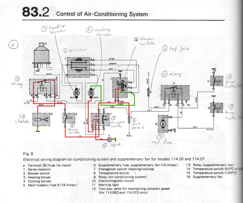
To power clutch and AC fan:
If you turn on the AC temperature switch (8), the vacuum pod movement triggers the changeover switch (7) and the power to heater fan is interrupted. Instead, the power starts flowing through main fuse (5), the blower switch (2) set to on, through changeover switch (7) to the AC fan (4). This circuit is closed by a ground to the blower switch set to highest blow.
At the same time the power flows from changeover switch (7), through temperature switch (8) into relay (9) to clutch (10). The relay is meant to deenergize the clutch when its circuit is closed by moving blower switch (2) to off.
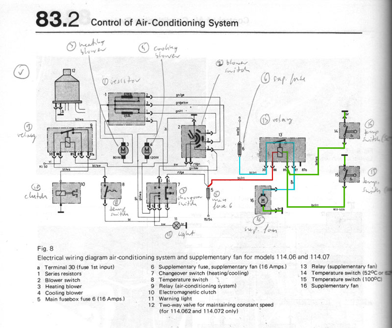
To power aux fan:
Power flows through main fuse (5) into relay (13) where if either of temperature switches (14 or 15) is closed to the ground due to high temperature, the circuit is complete and the relay is energized with current that goes through the supplementary fuse (6) powering the aux fan.